



Before we get started with part 3, I have a few updates regarding part 1 & 2.
I've found that the reset pad on the JTAG header is not actually a system reset (SRST) but a TAP reset (TRST), which isn't very useful for debugging. Here is the updated layout with the system reset signal added (this will allow the 'reset halt' command to break on the reset vector, before any instructions are executed).

In my case there wasn't a test pad for the SRST line, but there was a very small exposed bit of copper underneath the serial sticker, which was connected to the SRST pin of the CPU.
Ceriand on Reddit pointed out that the JTAG header matches the footprint of a MICTOR connector (38 or 40 pin one usually), so if you don't want to do any soldering you could get yourself a MICTOR connector and cable.
I've also found out the hard way that older PSUs don't like to be used at extremely low voltage (components inside them tend to explode), so I recommend buying a decent AC to Molex power adapter (don't get the cheap ones, they die after a day).
Lastly: because the JTAG header has an RTCK connector, you should be able to set adapter_khz in the openocd config to 0. The JTAG can then use adaptive clocking, which should prevent any timeout errors.
I've found that the reset pad on the JTAG header is not actually a system reset (SRST) but a TAP reset (TRST), which isn't very useful for debugging. Here is the updated layout with the system reset signal added (this will allow the 'reset halt' command to break on the reset vector, before any instructions are executed).
In my case there wasn't a test pad for the SRST line, but there was a very small exposed bit of copper underneath the serial sticker, which was connected to the SRST pin of the CPU.
Ceriand on Reddit pointed out that the JTAG header matches the footprint of a MICTOR connector (38 or 40 pin one usually), so if you don't want to do any soldering you could get yourself a MICTOR connector and cable.
 |
| MICTOR 38 connector |
I've also found out the hard way that older PSUs don't like to be used at extremely low voltage (components inside them tend to explode), so I recommend buying a decent AC to Molex power adapter (don't get the cheap ones, they die after a day).
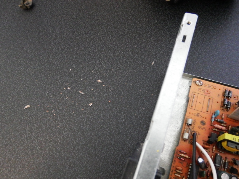 |
| Apparently glass fuses like to explode and send shards flying everywhere |
Lastly: because the JTAG header has an RTCK connector, you should be able to set adapter_khz in the openocd config to 0. The JTAG can then use adaptive clocking, which should prevent any timeout errors.
Bootstrap & Bootloader
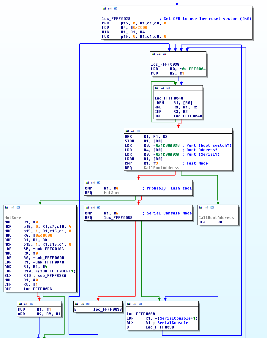
After some reversing I'm now convinced that the bootstrap code in Part 2 is not used during a normal boot. On execution it waits for some data on a port (most likely the serial port), then acts accordingly. If no data is found, the code goes into an infinite loop and the drive never boots.
On this CPU the 0x1C00A000 - 0x1C00AFFF range appears to be mapped to various ports and test pads all around the PCB. Now, because I don't have the money for an oscilloscope or decent logic analyzer I'm going to have to pass up on mapping these ports, even though it would make things easier.
All this code does is read some kind of switch which enters the system into a specific mode based on the value:
- 4 - Not sure, but it waits infinitely for a value on some port. My assumption is this code probably allows developers to read/write/erase the processor's internal flash.
- 3 - Jumps to the address in R4 (in my case this is 0, but that could be by design)
- 6 - A serial console which looks for ASCII bytes (r, w, j, h) on the serial port, allowing the developer to send read, write, jump, and halt commands.
I'm not familiar with how ports are mapped to memory, but 0x1C00A030 is always 0 while 0x1C00A03A is always 0xFFFF (which I assume means one is constant at a low voltage and the other constant at a high voltage).
Interestingly if we set a hardware breakpoints on "cmp R1, #3" and set R1 to 3, the code will jump to address 0 and boot normally (this is why I think 0 doesn't mean uninitialized). Let's see what's at address 0.
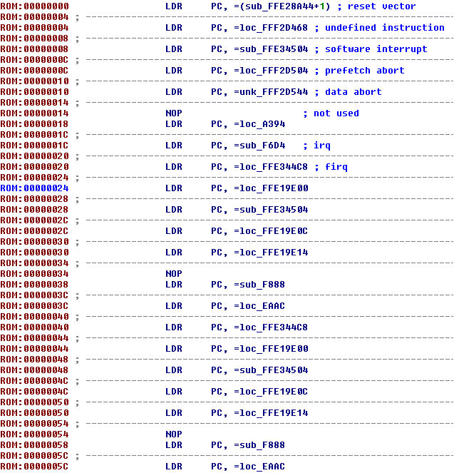
Address 0 is usually RAM, but there's already valid code here, so it's quite likely the CPU temporarily maps address 0 to some area of the internal ROM during boot. This is a standard ARM IVT, which you'd see at the boot address of any ARM devices; making me think the bootstrap at 0xFFFF0000 is only executed if the CPU detects a JTAG is attached. Until I can buy a decent logic analyzer and figure which port allows us to control the bootstrap mode switch, the only apparent way to boot the disk normally with a JTAG attached is to perform a "reset halt" then manually set R1 to '3' just before the check.
In this case the boot code is all over the place with massive gaps between sections, my next step will be to map, dump, and reverse it. I'd probably have done that already, but my power adapter didn't arrive until yesterday.
Part 4 (Working with spi flash): http://www.malwaretech.com/2015/05/hard-disk-firmware-hacking-part-4.html
SOCIAL SHARE CARD GENERATOR